Coolant
Level Warning Circuit on Land Rover Defender
Summary
The idea is that you will know when you run out of coolant before it becomes a critical overheating situation showing up on your car's temp dial (at best). I made such a warning unit for my car, a 1997 Land Rover Tdi CSW. We made a second one for Darryl Lampert's 1998 model.

In short, I use a Range Rover coolant expansion tank cap as
sensor for the coolant level. This is a direct replacement of the existing
expansion tank cap on the Land Rover Tdi's (don't know about the V8's and
2.8's; it does not fit on the TD5's) and has a built in float level sensor. For
the ease of simply screwing on the smart cap, and the honour of having both
Land Rover and VDO logo's on your vehicle's expansion tank
cap, you pay a few hundred Rand. However, this is still a lot cheaper than
float level sensors, with the right specifications but not straight
replacement, I was able to source elsewhere. The circuitry allows you to bypass
the circuit (a warning light in dash warns you it is bypassed) or operate it
normally. In normal operation, if the coolant level falls to just above the
bottom of the expansion tank, a buzzer sounds and the dash warning light comes
on. It also gives a brief system check (buzzer and light) when you start the
car up, provided it is set up correctly. It is easy to make up but less easy to
get to work properly because the relative resistances of the components play a
role. Be aware that the RR/VDO/LR cap does not have a simple magnetic read
switch incorporated; it is a more sophisticated switch. On Darryl's model we
learned the difference between production and a once off demo model (mine). The
components excluding the expansion tank cap is inexpensive (probably less than
R50 in total). The cap is over R300. One should be able to make the whole thing
and install it in a day (excluding buying components). I looked at a multitude
of options and this approach was the simplest I could find. The idea is that
you will know when you run out of coolant before it becomes a critical
overheating situation showing up on your car's temp dial.
Background
I have thought and investigated for more than a year around the issue of detecting overheating or cooling problems. There are many issues and different things that could be used or monitored. I would greatly appreciate more thought going into this as I do not think I have the final answer. However, what I have in place is a vast improvement over what there was (zip) and goes a long way to detecting EARLY enough SOME of the problems that may result in an overheated and seized engine. This was very important for me as the Tdi reportedly has seconds of life left under conditions of over-heating/lost coolant as opposed to the petrol versions with minutes. I looked at various possibilities of monitoring (reliably under adverse operating conditions) a range of engine and transmission temperatures. It seems thermo- couplers is the way to go but the equipment for this quickly adds up to several thousand Rand (if you have half a dozen or so points you monitor and you want warning circuits). And still you are reacting to a situation that has or is happening.
I also looked at sensors packages provided by VDO and SAC. VDO's is called the Automonitor (see www.civdo.co.za or email: vdo@civdo.co.za) These monitor 4 or so different engine parameters (VDO: Coolant level, coolant temp, and oil pressure or oil temp as an option. SAC's is called SafePower; see http://www.steves.co.za/main.htm: it monitors coolant level, exhaust temp, oil pressure, coolant temp). These systems cost over R3000 installed.
I looked at float level sensors and really wanted to get one that fits the radiator directly. I did not want to mechanically modify the radiator (which is an option) so I put a determined search into finding the appropriate part. Yes, there is one that is a straight screw in float level sensor in place of that plastic stopper; it also fits the thermostat housing top where there the same stopper is used on Defender. It is a Caterpillar part, but I have been unable to find out the part number. In fact, VDO themselves now makes such a float level sensor as part of their Automonitor; it is available separately but again I do not have the part number. I also looked into various float level sensors available in industry. These would have required drilling & fitting either the radiator or the expansion tank. Early on in this inquiry (in fact it spurred it on), I had a leak in the heater core, which resulted in loosing the coolant from the expansion tank. I only discovered this (on a trip) when the coolant had dropped to a level just being in the radiator.
When I came across the Range Rover cap idea It thought this is an easy partial solution as it can warn you of a whole class of problems resulting in coolant loss before the coolant loss becomes significant enough in itself to result in over-heating problems. It would for example picks up a blown gasket, which results in coolant entering the oil channels, and of course any coolant system leak.
In practice it turns out that that installation is not as simple as it looks but still a lot simpler than some other options. One problem is to have an installation design, which has a low false alarm rate, especially on rough terrain, and with the engine working hard (high end of temp range). What I have seems to deliver this, but it does not warn you of all over-heating conditions. For that I watch the temp gauge like a hawk and have installed an oil temp gauge (plus oil pressure gauge).
One of the major drawbacks of measuring coolant level alone is that you do not know if the coolant is effectively circulating, i.e. you do not know the condition of the water pump. If the coolant is high you can only see the results of insufficient coolant circulation in the temp gauge -- too late then in my thinking. Problem is there are many other conditions that only show up in the temp gauge stalking red (e.g. failing viscous coupling on fan, as I have had). All considered, I would like to measure and have alarms go off when out of parameter conditions occur on: Oil pressure, oil temp, coolant level, coolant temp, exhaust pressure, charging current, and timing belt % wear. I have stopped "adding" things to my 1997 Defender 110 Tdi with 112000km. If I get a newish TD5 I may go for a SAC or VDO monitor system from the start and leave it at that. Rather then spend the time driving and socialising than designing and fitting preventative systems. But the coolant level warning thing was worth the effort I think.
Warning
System Photographs
Photograph 2 Coolant level sensor cap installed in expansion
tank on Tdi. Note cabling sleeved in ribbed sleeving and fully insulated spade
terminals.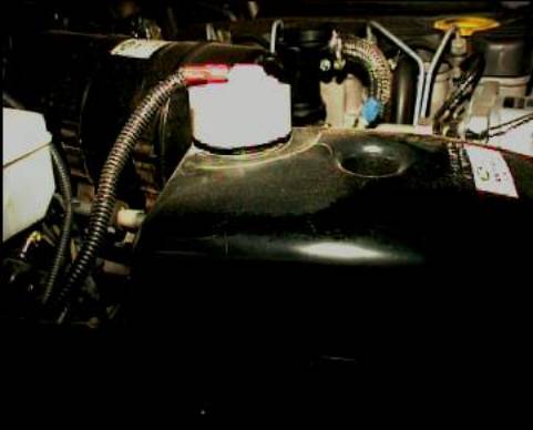
Photograph 3 Override switch at green arrow; switches
warning system between normal (on) operation and bypass (warnings disabled but
warning light on dash lit to remind of bypass condition)
(Red arrow is rear
spot light switch; can also be switched on from rear.)

Photograph 4
Dash warning light. This light is unused and although not white on the
instrument panel itself, the logo is there. It is between the trailer turning
indicator light and the break warning light. It is a red warning light. You will
need a small bulb.
Warning
System Circuit Diagrams and Construction
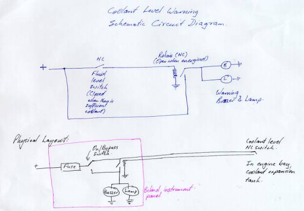
Figure 1: Overall Schematic
Circuit Diagram.
This diagram shows the overall picture. The RR coolant tank cap has a "normally closed" switch, meaning that when the coolant is sufficient high in the tank the switch is closed. This is a fail-safe design, in that any condition creating a short or cut in the wiring will result in the coolant level being shown "low" when in fact it is not. However, this complicates the design of the warning part, as one must "invert" the signal form the coolant level sensor: The warning circuit must be "off" when the sensor is "on" and "on" when the sensor is "off (open)". The relay is used to achieve this: The relay is chosen to be closed when not energised and open when energised. While on get such relays (like the reed relay used on my car) most relays have both NC and NO contacts and it is a matter of choosing the correct set of contacts.
By using the relay as open when energised, one can use the contacts that are closed in the un-energised condition, to pass a current through which shows the system is working -- a kind of test condition like that when the car is switched on and all warning lights are on for a short while. This is the purpose of the +12V line bypassing the float level sensor going directly to the relay in the top part of the diagram.
The bottom part of the diagram shows the physical layout of the circuit. I placed the section marked in purple behind the instrument panel inside the car and took the wire to the float level sensor through the firewall using the existing holes and grommets for instrument wiring and heater controls. I included both a buzzer and a warning light as alarm signals. For the warning light I used one of the existing dash warning lights that is currently unused, namely the one that would be used for the transmission temperature warning light in an auto transmission (RTFM).
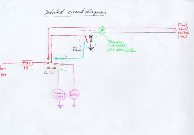
Figure 2: Detailed
circuit diagram (The red "tion live" on
left should read "Ignition live")
The actual circuit is slightly different from the schematic given in Figure 1.
The first difference is the compound switch (called a triple pole, double through switch). This switch has two functions, namely (a) to bypass the warning circuit which enables you to switch it off if it malfunctions or if you choose to drive with a low expansion tank coolant level and (b) to warn you that the warning circuit is bypassed in case you forget to re-set it. It achieves (a) by simply not powering up the float level sensor and consequently not the relay. It achieves (b) by powering the dash warning light (but not the buzzer) when it is in the "off" position. Consequently the dash warning light is on also when the warning circuit is "Off", but the buzzer and the dash warning light are both on when the coolant sensor senses low coolant (or if there is short on that circuit). Note the connections between the different terminals on the switch. The centre or "common" terminals are used for (1) the +12V power supply (2) the + terminal for the dash warning lamp and (3) the + terminal for the buzzer. More details on this are given in Figure 3 below.
The second difference is the green marked resistor bypassing the float level sensor (coolant tank cap terminals). On my car this resistor was not required, on Darryl's car we used 2.2 K Ohm resistor in that position. I suggest you use a 4.7 K Ohm variable resistor in that position, which must be adjusted once the circuit is installed to the correct setting, for the following complicated reason (You can skip the explanation but remember to adjust it as discussed under installation):
The LR/RR/VDO expansion tank cap does not have a simple magnetic switch inside, but some more sophisticated probably solid state switch. This switch shows up as a 680 Ohm resistor when passing a current through the float level sensor. This means that the relay may or may not close when current is applied through the float level sensor, depending on the actual relay specifications. In my case the relay used required a very low current (around 12-15 milliamps) to close, but the relay we used for Darryl's car required about double this. The purpose of the resistor is to provide additional current to the relay to enable it to close when it should. However, the resistor must pass little enough current so that the relay opens when it does not get the additional current form the float level sensor, i.e it opens when the float level sensor opens even if the relay gets the bit of current in through the resistor. The purpose of the variable resistor is to allow you to experimentally adjust this current, as it also depends on the voltage supplied by the alternator. While you can look up the specs for the relay you use, and use the current-to-open and current-to-drop-out values, together with accurate measurements of the voltage in the specific installation, to calculate this resistor value, a variable resistor will make it easier to find the correct resistance in practice.
There is a third modification you should consider making, namely using power from a stabilised source. This will make it easier to adjust the resistor to the correct setting, regardless of voltage drops due to engine, alternator and battery variables. Such a voltage stabiliser is the National Semiconductor LM317 voltage regulator. Although it would be wise to use this, neither Darryl's nor my car has got this in.
The funny upside down triangles in the above circuit are connections to ground. In the actual construction the negative/earth side of the warning lamp, buzzer and relay were all collected in one point and securely connected on an earthling point. (if your circuit does not operate as expected, first check the earthling connections; Why do I know?)

Figure 3: Details of switch connections.
Note that the line leaving the picture below "Warning light" goes to ground/earth.
The purpose of the switch is discussed above.
In construction, be careful that the wiring and soldering on the terminals of the switch do not short circuit when done. These switches are small and the car type wiring tends to be relatively thick. While you do not need such thick wiring it makes for a stronger set-up, but you may then have the switch terminals touching. Also be careful when soldering these witches that too much applied heat does not damage them. A safe approach is to allow a few minutes between soldering each terminal.
Installation
Basically you have to make the thing, like it says in the diagrams. I did this first and tested it before actually putting in the car(s).
Some notes on the installation:
I take power off the switch for the rear window demister, on the positive side. There are other options but this one seems safe. I cleared the insulation and soldered the wires together. Do not use the warning flashers switch because this is an always live circuit; you want to use one that is only live when ignition is switched on.
Before you put the spade terminals on the cable going to the expansion tank cap, take it through the firewall holes and grommet. This is much easier than getting it through those holes with the terminals on. We used spade terminals that are fully covered by insulation.
I sleeved all wiring in ribbed sleeving and cable tied every thing in sight to prevent chafing.
I taped all parts going behind the dash/instrument panel together with insulation tape so that no open terminals are showing and fixed it in place with double sided tape.
Be careful when putting the lamp into the dash: One easily dislodges the wiring to other warning lights and instruments; check this after you closed up everything again.
I suggest you do the adjustment to the resistor before finally installing the circuit. Leave the existing expansion tank cap in place, and test your circuit with the new cap outside; this can be done by moving the while collar up (to simulate full tank) or moving the collar down (loss of coolant). Do this with the car off (everything must be off, including you warning circuit. Then switch engine on: Adjust the resistor so that you get the buzzer/warning light to go out while the collar is in the up position (tank full) but goes on immediately when the collar is moved down (loss of coolant). For a relay with a 365 Omh coil resistance we found the value of the resistor needed to be 2.2 K Ohm. You may want to pre-set the variable resistor to about this level using a multimeter before you start, in order to have a good starting point. When you have found this position, put some glue on the variable resister to prevent it from moving again. As I said, my car did not require this resistor, and because we did not use a variable resistor it took a couple of tries before we found the right resistance to make Darryl's work properly. A variable resistor will avoid much effort in finding the correct setting.
If you get tings just right, you will have the following additional feature: When the "ignition" is turned on, while turning the starter motor, the voltage level drops to such a level that the relay does not open, even if the float level sensor is on the closed position. The buzzer and dash light will then come on for the time it takes the engine to start, i.e. while the starter motor is running. This gives a brief warning light and buzzer signal saying the coolant level warning circuit is functional. As soon as the engine starts running the alternator kicks in and the voltage goes up to normal, the relay opens and the warning buzzer and light goes out. I find that these on/off of the buzzer and light co-incides with the charging warning light going out, so the overall effect is a test of the warning lights and circuits.
Warning
System Part List
Parts:
·
Float level sensor cap;
·
switch;
·
relay,
·
spade terminals with covers,
·

·
buzzer,
·
fuse holder and 1 amp fuse;
·
approximately 2 m lenth of double cored wire
Not
in photograph:
·
Miniature bulb for dash warning light,
·
miniature spade terminals for dash warning light connections (2),
·
4.7 K Ohm variable resistor,
·
ribbed wire sleeving,
·
cable ties.
1.

The Range Rover/Land Rover/VDO float level sensor expansion
tank cap, part number PRC 7925
2. Relay: 12 Volt with both normally closed and normally open
terminals. Look for one with a coil current of around 20-30 milliamps. It will
have coil resistance of around 400-600 Ohm. This relay is always energised when
the  ignition
is on and you do not want to use an unnecessarily heavy current drain relay.
ignition
is on and you do not want to use an unnecessarily heavy current drain relay.
3. Switch: Triple pole, double through. This switch should not be a
three position (ON-OFF-ON), but a true double through (ON-ON) only. If you have
the ON-OFF-ON type you can switch the whole circuit OFF without the warning
lamp to tell you that the warning circuit is bypassed. This is not a good idea.
If you can not get a triple terminal switch use a 4 terminal switch and leave
one set of contacts unused.
4. Buzzer. Use any 12V buzzer, but find one you think will be loud enough. Mine is a constant sound buzzer, but Darryl's is a pulsing sound one and is probably more attention grabbing. The current usage is not critical on this because it is hopefully not on for long.
Johan Strumpfer
February 2001.
sysprac@iafrica.com